Types of Prefabricated Bridge Elements and Systems for Bridge Construction
The most used prefabricated concrete elements for bridge construction are prestressed I beam, prestressed box beam, prestressed channel, and slab span. In this article different types of prefabricated bridge elements and systems will be discussed.
Types of Prefabricated Bridge Elements and Systems for Bridge Construction
- Precast and prestress slab spans
- Multi stemmed beams
- Prestressed double tee and channel
- Prestressed inverted channel
- Prestressed single tee
- Prestressed I beams
- Prestressed box beams
- Prestressed bulb tee
- Segmental construction
- Prestressed subdeck panels
- Precast and prestress deck slabs
- Precast parapet
- Substructure elements
- Precast culverts
Precast and Prestress Slab Spans for Bridge Construction
Precast slab members can be constructed in various widths, depth, and length to built spans up to 15 m. shorter spans might be normally reinforced and cast in simple precast plants whereas long spans are commonly voided and post tensioned or prestressed.
It is easy to fabricate, transport, and erect precast slabs. Normally, span of precast slab is 3-9 m and prestressed slab span ranges from 6 to 15 m. Figure-1 shows cross section of precast voided and solid slab.

Fig.1: Precast and Prestress Slab Spans for Bridge Construction
Multi Stemmed Beams for Bridge Construction
Multi stemmed beams as shown in Figure-2 is constructed in different length and width and its span is usually between 8 and 15 m. shear between beams is transferred through weld plates and grouted keyways.
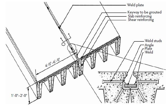
Fig.2: Multi Stemmed Beam for Bridge Construction
Prestressed Double Tee and Channel for Bridge Construction
Compared to building construction, prestressed double tee and channel employed in bridge application are constructed with higher prestress, wider webs, and thicker flanges. This prefabricated bridge element types is used for medium length spans; ranges is between 6-18 m.
Similar to multi stemmed beams, weld plates and grouted keyways transfer shears between beams. In situ concrete is poured as an overlay while channel and double tee member are overlaid with asphalt.
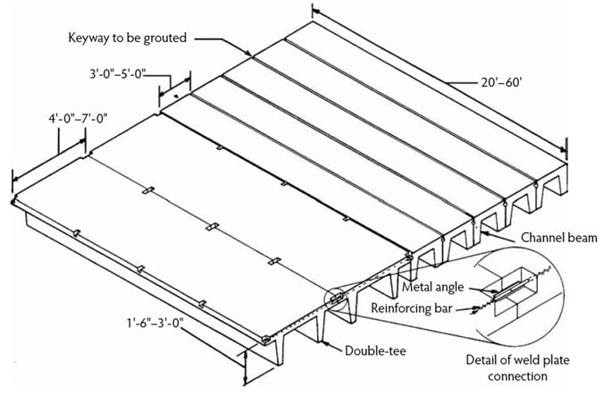
Fig.3: Double Tee and Channel Element for Bridge Construction
Prestressed Inverted Channel for Bridge Construction
This element is either casted in ordinary channel formwork and then inverted prior to installation or cast in inverted position. In the inverted position, longer spans can be constructed because higher prestressing can be provided in the beam bottom and spans are usually 9-24 m. Moreover, deck surface can be achieved by filling channels with in situ concrete.
Inverted T beam is an alternative to prestressed inverted channel. They can be installed adjacent to each other, after that a solid member is constructed by placing cast in place concrete between the webs of the tee and over the tops of the stem. Figure-4 show a prestressed inverted channel member.
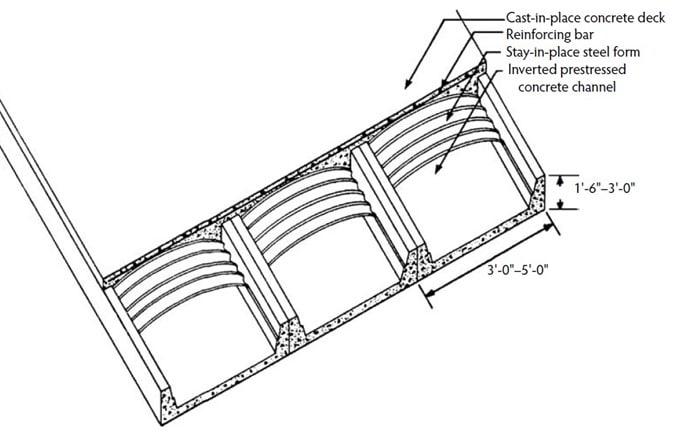
Fig.4: Prestressed Inverted Channel
Prestressed Single Tee Element
For building applications, producers employ formworks to construct prestress single tee, and the same formworks can be used to cast short span prestressed single tee elements for bridge construction but larger prestressing should be provided to bear greater loading.
Long span prestressed single tee beams can be constructed for highway loadings. Due to the fact that single tee beams are unstable by design and overturning may occur at construction site provided that the beams are not supported until keyways are grouted and diaphragms are casted.
Deck surface and the connection between tees are achieved by providing site placed concrete. The prestressed single tee spans between 9 and 24 m. Figure-5 provides details of prestressed single tee element.
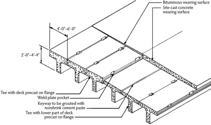
Fig.5: Prestressed Single Tee Element
Prestressed I-Beams for Bridge Construction
The standard ASSHTO recommends different prestressed I beam cross sections which simplify the design and used for mass productions. The beams precast I beams are economical for spans that ranges from 12 to 30 m, and can be constructed in different depths and widths.
Moreover, long spans can be produced by connecting the beams end to end and then post tensioning together. The prestressed I beam installations are quicker than site in place concrete beams. Figure-6 shows I beams with different cross sections.
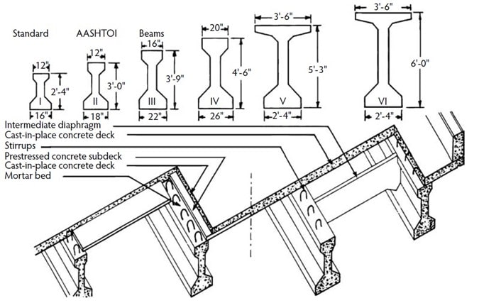
Fig.6: Prestress I-Beam for Bridge Construction
Prestressed Box Beams for Bridge Construction
This type of prefabricated element might precast in different widths, depths, and lengths to construct spans of nearly 15 to 30 m. prestressed box beams are positioned adjacent to each other then tensioned in transverse direction after that a layer of asphalt is employed for cover the surface.
Moreover, diaphragms are used to connect prestressed box beams which are placed close to each other and site cast concrete is applied for both diaphragm and the deck.
Furthermore, a procedure is established for the transverse design of concrete box beams without composite topping. According to this methodology, post tensioning should be used after the grouting of shear keys.
Finally, it is claimed that this design provides a more durable product. Figure-7 shows a prestressed box beam.
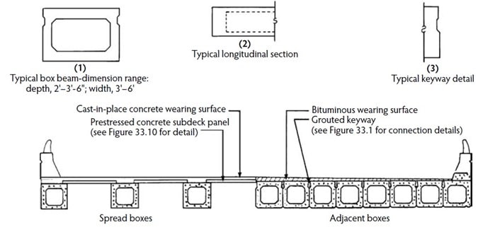
Fig.7: Prestressed Box Beam for Bridge Construction
Prestressed Bulb Tee
AASHTO girders are modified which is more economical for spans of larger than 24 m. the beams possess large section modulus to weight ratio and beams with span of larger than 54 m have been produced. a prestressed bulb tee is illustrated in Figure-8.
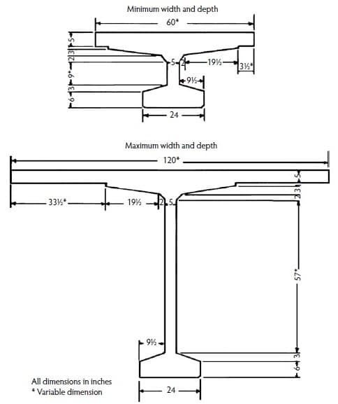
Fig.8: Prestressed Bulb Tee for Bridge Construction
Segmental Construction of Bridges
The elements are post tensioned in longitudinal direction, prestressed in transverse direction, match cast, full width, and can be applied for different span lengths which ranges from 15 to 122 m.
Elements are installed on false work or assembled on a truss that is supported pier to pier. However, balanced cantilever, incremental lunching, or progressive placing is used for the erection of elements when the span is long. An economical procedure is developed to replace the top slab of precast post tensioned segmental bridge; therefore deck deterioration will not need the replacement of super structure. Figure 9 illustrated the post tensioned segmental construction.
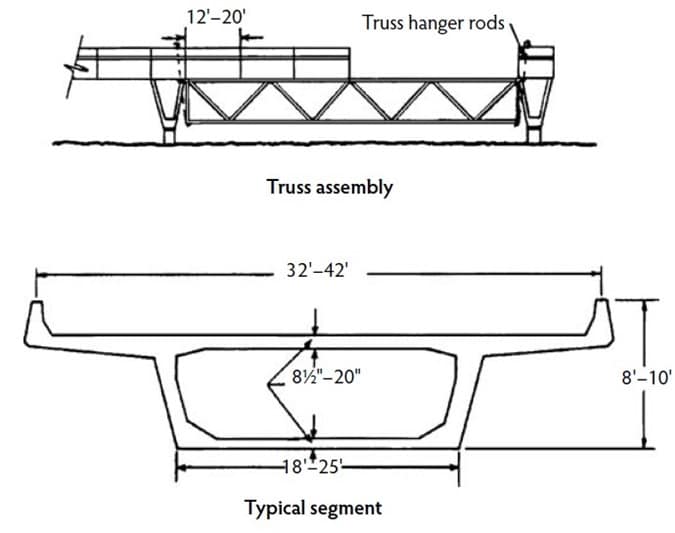
Fig.9: Post Tensioned Segmental Construction of Bridges
Prestressed Subdeck Panels for Bridges
The prestressed subdeck panels as shown in Figure-10 are constructed in various widths and depths and commonly 1.2m to 2.4m. The length is based on the spacing of beams that support the panels. The thickness of panels is 89mm and placed in grout of 13mm thickness. A reinforced deck is produced by placing cast in place concrete over the panels.
Moreover, the panels can be placed with small cranes and number of labors, and temporary forms or platforms to work from is not needed. Cracks are commonly developed in the cast in place concrete above the joints. In contrary, if the panels are installed on prestressed girders on short spans, the cracks will not be very noticeable.
Finally, the prestressed subdeck panels offer rapid construction and economical deck.
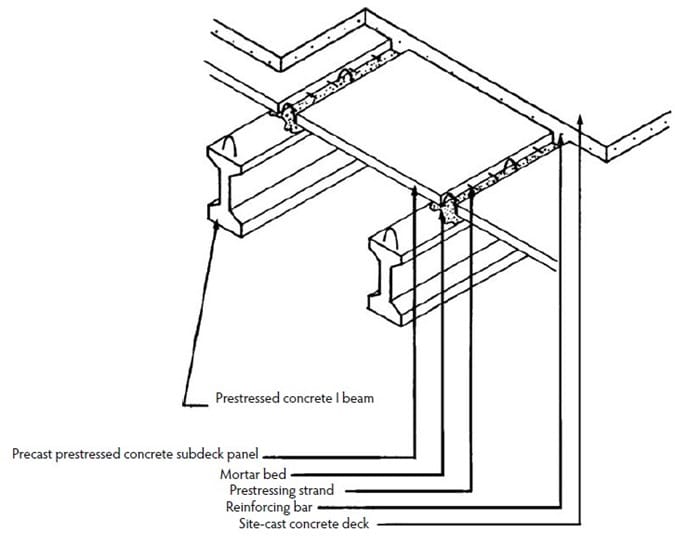
Fig.10: Prestressed Subdeck Panel for Bridges
Precast and Prestress Deck Slabs for Bridge Construction
Generally, decks are the first bridge element that damaged or deteriorated and hence need strengthening. If the deck bridge is need strengthening or replacement and the traffic is high, it is recommended to do the work during the off peak period.
Several replacement methods are established employing prefabricated deck slabs and most strategies make use of transverse segment connected to supporting beams though hydraulic cement or rapid curing polymer.
Grouted keyways, cast in place concrete, and post tensioning transfer the shear between neighboring slabs. The compost action is obtained by the application of studs on steel beams that extend into the slab voids that filled with hydraulic cement or polymer in later times. Figure-11 should details of prestressed deck slab.
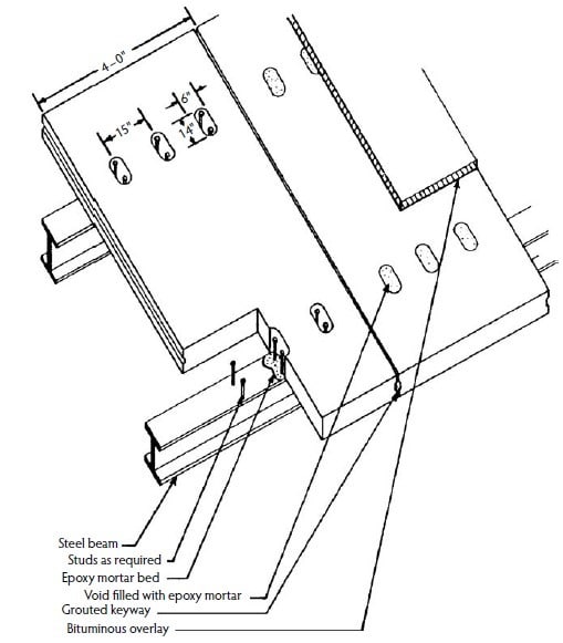
Fig.11: Prestressed Deck Slab for Bridge Construction
Moreover, it is reported that, deck slabs are more economical compared to cast in place slabs. This is because not only the construction time is decline but also a structural efficiency is achieved using prestressing and post tensioning.
There have been several attempts to improve connection of slab decks to steel beam and prestressed beams. Particular loop bar reinforcement is made by which live load can be distributed over transverse and longitudinal joints.
Added to that, a full depth precast prestressed concrete bridge deck is constructed that involves stemmed slabs, transverse grouted joints, longitudinal post tensioning, and welded threads and headless studs. Not only does the deck slab have smaller thickness compare to ordinary deck slabs but also it can be built quicker.
Furthermore, prestressed deck slabs are commonly used in considerably significant bridge deck replacement projects for example the Woodrow Wilson Bridge shown in Figure-12. And full depth transverse deck slabs used and replaced the truss spans of the deck on I-95 in Richmond.
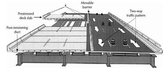
Fig.12: Woodrow Wilson Bridge
Finally, longitudinal, partial depth, or full depth deck slabs which are precast on one or more concrete or steel beams have been utilized successfully.
Precast Parapet for Bridges
it has standard shape and mass produced easily and there are various connections which can be used to anchor the precast parapet. it has been used in several locations but there is a problem with water and chloride solution leaking between the top of the deck and the base of parapet and this issue might slow down the acceptance of precast parapet. Figure-13 shows a precast parapet.
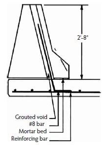
Fig.13: Precast Parapet for Bridges
Substructure Elements for Bridges
Generally, the construction of substructure need more time compared to superstructure and this time can be decreased by applying prefabricated element. The majority of substructure elements are prefabricated for instance piles, piers, pier cap, abutments, and wing walls.
Figure-14 illustrates the abutment and wing walls installed on temporary pads and anchored with weld plates and cast in place concrete. The construction is simplified by precast abutment and wing wall with the footing and place on site cast footing.
The most famous application of prefabricated pier is located in Linn Cove Viaduct as shown in Figure-15. The whole bridge structure elements were prefabricated to reduce the environmental impact. Until the location of the pier is reached, precast segmental superstructure segments were placed and post tensioned.
The drilling of the holes in which prestressed pile are installed were carried out from cantilevered superstructure, and then precast segments were placed and post tensioned.
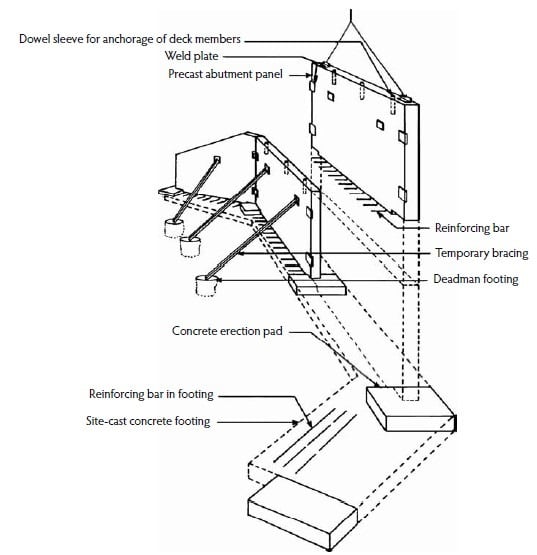
Fig.14: Precast Abutment and Wing Wall

Fig.15: Prefabricated Pier Segment for Bridges
Precast Culverts for Bridge Construction
It is possible to employ precast culverts instead of bridges if the cross section does not restrict the flow of water. Culverts are placed easily, does not have a deck to damage, and rarely need extensive plans.
Precast culverts designs might include inverted U, pipe, box, and arch. Concrete pipes are used for spans of 0.3 to 3m and concrete box can be employed for spans of 1.2 to 3.7m. Precast U shaped culverts and arch shapes applied for spans of 4.9m and 12m, respectively.
Comments