Seismic Retrofitting of Bridge Abutments -Methods and Details
There are two types of abutments which are employed in bridge construction namely: monolithic as shown in Figure-1 and seat type as it can be seen in Figure-2. The former is usually utilized in short span bridge construction whereas the latter is applied in long span bridge construction.
The possibility of severe seismic damage is substantially higher in the case of monolithic type than seat type because the backwall in the latter type could be designed to work as a fuser and restrict the bridge pile earthquake damages.
The backwall damage due to seismic loads is tolerable since it will not lead to the total collapse of the bridge and prevent bridge pile extreme seismic damage.
There are various issues that bridge abutments may exhibit during earthquakes for example inadequate seat length in the case of seat type abutment, large gap between end diaphragm of bridge superstructure and backwall, inadequate transverse and/or longitudinal shear strength, and vulnerable end diaphragm in the case of monolithic abutment.
So, it is required to retrofit the bridge to eliminate these seismic vulnerabilities. Different seismic retrofit technique are discussed in the following sections.

Fig.1: Monolithic Bridge Abutment
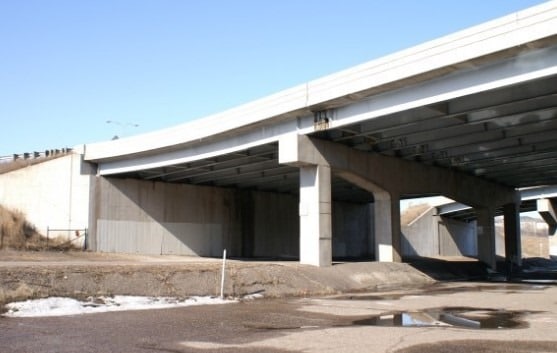
Fig.2: Seat Type Bridge Abutment
Table of Contents [show]
Methods of Seismic Retrofitting of Bridge Abutments
- Seat extenders and catchers
- Use concrete, steel, or timber to fill the gap between backwall and end diaphragm of bridge superstructure
- L bracket on superstructure soffit
- Shear Keys, Large CIDH Piles, Anchor Slabs, and Vertical Pipes
Seat Extenders and Catchers for Retrofitting of Bridge Abutments
Seat extenders are commonly constructed of concrete as shown in Figure-3 or steel brackets as shown in Figure-4 attached to the existing face of abutments or caped beams in order to decline the possibility of bridge girder unseating during earthquakes.
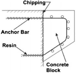
Fig.3: Details of Concrete Seat Extender

Fig.4: Details of Steel Bracket Extender
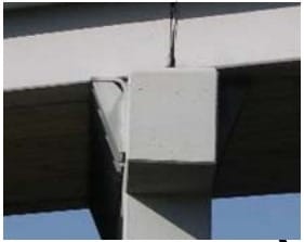
Fig.5: Seat Extender
The design of seat extender is similar to corbel design and there are several forces that must be considered while the steel, which is employed to join seat extender to the face of cap beam or abutment, is designed.
For instance, shear friction for vertical loads and tensile forces generated by shear forces when bridge girder moves longitudinally and drive the extender away from abutment or cap beam face in addition to compression strut and bearing loads under bridge girder.
It is recommended to deliberately rough up abutment or cap beam concrete face in order to achieve satisfactory bond between existing concrete and seat extender.
Regarding seat catcher, it should be introduced if bridge superstructure settled more than 150mm after bearing failure. Therefore, the purpose of catcher provision is to restrict superstructure settling to as minimum as 50mm in addition to increase seat width.
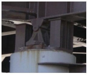
Fig.6: Catcher Provided for a Vulnerable Bearing In Missouri, USA
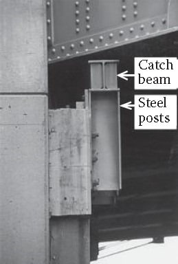
Fig.7: Catcher Beam used for Steel Girder
Seat catcher is placed on the top of the abutment of cap beam and its design is similar to that of seat extender.
Lastly, it should be remembered that adequate space need to be left for bearing inspection and replacement while the provision of catcher is considered.
Use of Concrete, Steel or Timber to Fill the Gap between Backwall and End Diaphragm of Bridge Superstructure
Occasionally, considerably large gap is present between backwall and end diaphragm of the bridge. This could be a weak point for the bridge during earthquakes since the bridge column needs to deflect crucially so as to activate the back-fill soil.
So, filling this gap with concrete, steel, or timber is assumed to be a seismic retrofit technique because it involves the backwall and the backfill material to contribute the decrease of seismic damages.
It is recommended to pay attention to the thermal movements while this is filled with suitable material.

Fig.8: Abutment Blocking
L Bracket on Superstructure Soffit
It is the addition of L shaped steel to the flanges of steel I-girder of a bridge. The L shaped steel works like bumper that transfer longitudinal reaction from the superstructure to the abutment and eventually to the soil.
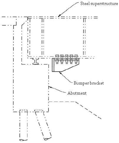
Fig.9: Bracket at Bridge Abutment
Shear Keys, Large CIDH Piles, Anchor Slabs and Vertical Pipes
The most suitable retrofit strategy for short span bridge is driving the seismic loads away from columns and footing to the abutments. This can be achieved strengthening or anchoring the abutment and restricting its movement during earthquakes and consequently most of loads would affect abutments.
Techniques that may be employed for bridge abutment modification or anchoring includes seismic anchor slabs, anchor pile, vertical pipes, or shear keys.
It is recommended to utilized either anchor piles or vertical pipes provided that the bridge is substantially curved or skewed because of the complex geometry of the bridge.
For instance, as the bridge rotates away from the abutment, there would be no force that withstand this movement. That is why the addition of anchor piles at cute corners of the abutment is considerably significant since it resists such movement.
Comments